 The ATLAS Shielding Photo Collection
 The ATLAS Shielding Photo Collection
|
This site contains a collection of photos
taken in the shielding project in the ATLAS experiment.
INDEX |
|
     |
|||
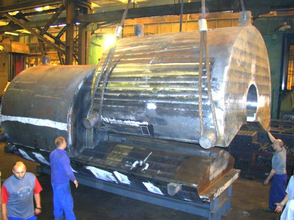
 Photos from the acceptance test of the massive cast ductile iron JF shielding pieces at the Skoda Steel company in June 2003. Slide show of the photos. Video |
 Photos of the JF octagonal ductile iron pieces taken by Skoda in October 2003. Slide show of the photos. |
Photos of the JF octagonal ductile iron pieces taken at Skoda in November 2003. |
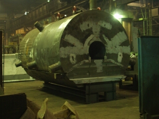 Photos of the second set of JF core pieces. Taken by Skoda in December 2003. Slide show of the photos. |
 Photos of the JF ductile iron pieces after painting at Skoda in October 2004. Slide show of the photos. |
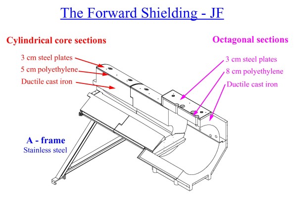
 Photos at the Tranza company in 2004 of the steel plates that are used as a photon filter on the JF shielding. Slide show of the photos. |
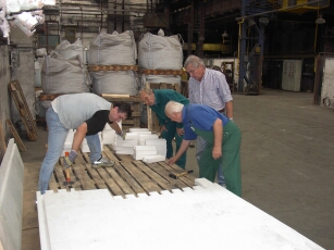 Photos of the assembly in September 2004 of polyethylene bricks into strips and plates. The polyetethylene bricks were manufactured by the Kopos Kolin company and are used as neutron shielding in the JF shielding. Slide show of the photos. |
 Photos of the cermony in November 2004 when Skoda Hute was awarded the ATLAS supplier award. Slide show of the photos. |
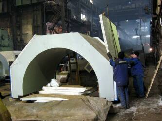 Assembly of the JF shielding at Skoda during the spring of 2005. Slide show of the photos. |
 Test of the JF A-frames in Serbia in March of 2005. Slide show of the photos. |
Storage of the JF A-frames in the North Hall after they have arrived at CERN in April of 2005 |
Visit at Skoda in June 2005 after the assembly of the JF shielding. |
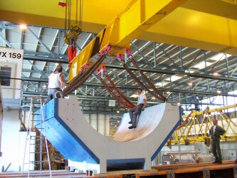 The JF pieces arrive at CERN during July-September 2005. Slide show of the photos. |
 The JF supports after they arrive at CERN during July-September 2005 . Slide show of the photos. |
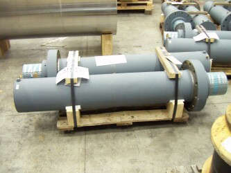 The hydraulic jacks for the JF lifting frame after they have been delivered from the Hunger company in December 2005. Slide show of the photos. |
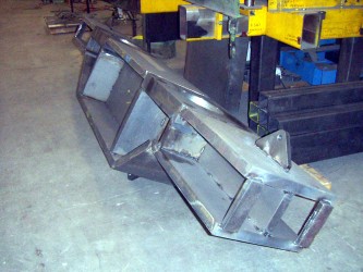 The JF lifting frame during manufacture at the Gonzales company in March 2006. Slide show of the photos. |
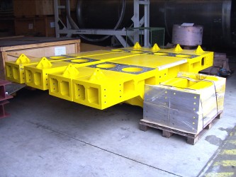 The JF lifting frame after it was delivered to CERN in July 2006. Slide show of the photos. |
The VJ beampipe in February 2007. |
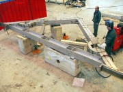 The A-frame is being modified in building 180 at CERN. Slide show of the photos. |
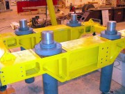 The JF lifting table is being assembled in building 180 at CERN. Slide show of the photos. |
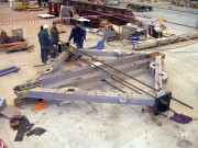 Load test of the modified A-frames to 189 tonnes at CERN in April 2008. Slide show of the photos. |
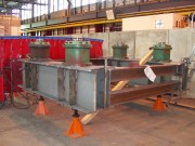 The construction of the extension table. Slide show of the photos. |
Test assembly of the JF core. |
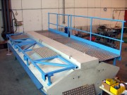 Construction of the JF platform. Slide show of the photos. |
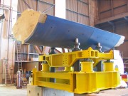 Test of the JF lifting table & extension table. Slide show of the photos. |
The A-frame is being installed in ATLAS. |
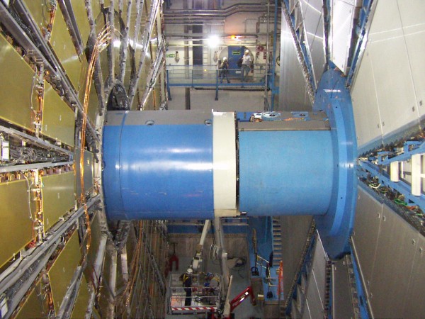
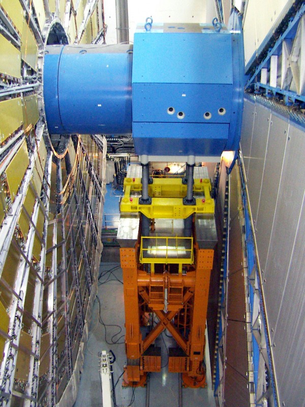
Installation of JFC1 on side C in ATLAS in June 2008. |
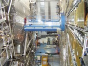 Installation of JFC1 on side A in ATLAS in June 2008. Slide show of the photos. |
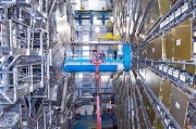 The VJ beampipe installation in the ATLAS cavern. Slide show of the photos. Video |
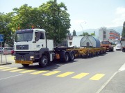 Installation of JFC2 on side C in ATLAS in June 2008. Slide show of the photos. Video |
Installation of JFC2 on side A in ATLAS in July 2008. |
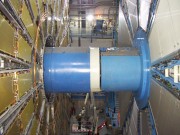 Installation of JFC3 on side C in ATLAS in July 2008. Slide show of the photos. Video |
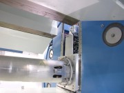 Installation of JFC3 on side A in ATLAS in July 2008. Slide show of the photos. |
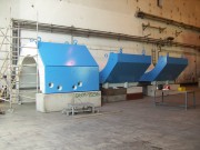 The Octagonal pieces after painting in September 2008. Slide show of the photos. |
Removal of JFC1 using the lifting table. |
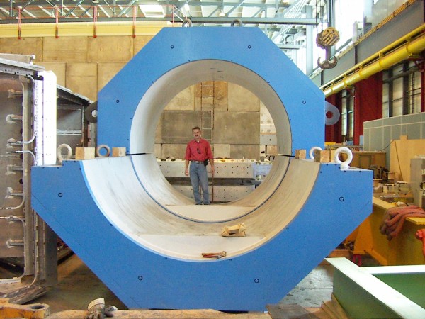
After installation of the octagonal shielding on side A in August 2009. |
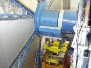 Installation of the lower octagonal piece on side C in August 2009. Slide show of the photos. |
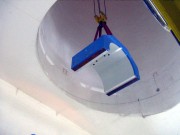 Installation of the upper octagonal piece on side C in August 2009. Slide show of the photos. |
||
   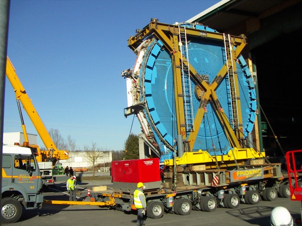 |
|||
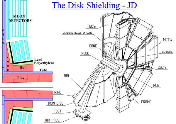
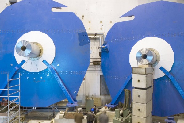
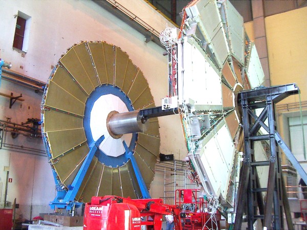
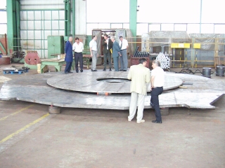 Photos of the JD disk taken at the Lola factory in Serbia in July 2004. Slide show of the photos. |
Photos of the JD disk taken at the Lola factory in Serbia during the testassembly in October 2004. |
 Photos taken at CERN after the delivery from the Lola company of the JD shielding disk in December 2004. Slide show of the photos. |
 Photos taken at CERN after the delivery from the Resarm company of polyethylene cladding for the JD shielding. Slide show of the photos. |
 Photos in Armenia in 2004 of the brass part of the JD hub. Slide show of the photos. |
Photos taken at CERN after the delivery of the JD shielding hub from Armenia in January 2005. |
 Photos taken during a visit to the SIMIC company in April 2005. Slide show of the photos. |
 The manufacturing of the JD cone pieces in Armenia during the spring of 2005. Slide show of the photos. |
 Photos of the JD cone pieces after their arrival at CERN in September 2005. Slide show of the photos. |
 Photos of the JD plug pieces after their arrival at CERN in September 2005. Slide show of the photos. |
 Photos of the JD disk being stored in the North Hall during 2005. Slide show of the photos. |
 Photos of the JD Jacking Block Shoes after their arrival at CERN in September 2005. Slide show of the photos. |
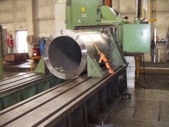 Photos of the JD Stainless Steel Tube taken at the SIMIC factory in September 2005. Slide show of the photos. |
 The JD ribs during manufacturing by Nortemecanica in Spain during October 2005. Slide show of the photos. |
 The JD lead for the cladding after its arrival to CERN from Pakistan in 2005. Slide show of the photos. |
 The assembly of the JD shielding in December 2005. Slide show of the photos. |
 Photos of the JD feet in December 2005. Slide show of the photos. |
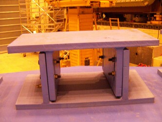 The JD ring pieces after they have arrived at CERN in December 2005. Slide show of the photos. |
 The JD Stainless Steel tube after its delivery to CERN in December 2005. Slide show of the photos. |
 The JD rotation frame after its delivery in November 2005. Slide show of the photos. |
 The JD installation frame is being manufactured by Heavy Machinbuilding in Bulgaria in December 2005. Slide show of the photos. |
The test assembly of the first JD lifting frame in Bulgaria in January 2006. |
 The JD Hub movement system in May 2006. Slide show of the photos. |
 The manufacture of the JD liftinglug in May 2006. Slide show of the photos. |
 The JD installation frame is being modified at CERN in May 2006. Slide show of the photos. |
The test assembly of the second JD lifting frame in Bulgaria in May 2006. |
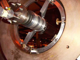 Test of the support of the VA beampipe to the JD shielding in June 2006. Slide show of the photos. |
The first rotation of the JD shielding in June 2006. |
 The assembly of the JD ribs in June 2006. Slide show of the photos. |
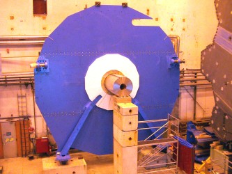 The second rotation of the JD shielding in July 2006. Slide show of the photos. |
 The assembly of the second JD in October 2006. Slide show of the photos. |
The displacement of the JD in December 2006. |
 The first rotation of the second JD in December 2006. Slide show of the photos. |
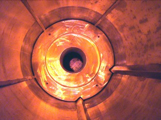 The assembly of the second JD in February 2007. Slide show of the photos. |
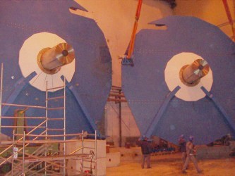 The final rotation of the second JD in March 2007. Slide show of the photos. |
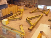 The assembly of the JD installation frame in the autumn of 2007. Slide show of the photos. |
|
Modifications to the hub movement system in July 2007. |
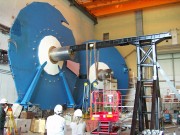 Installation of the SW bridge and frame. Slide show of the photos. |
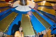 Installation of TGC chambers on the JD in July 2007. Slide show of the photos. |
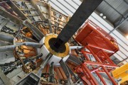 Installation of CSC chambers on the JD in September 2007. Slide show of the photos. |
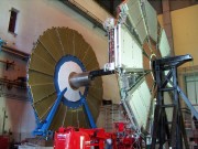 The assembly of the Small Wheel. Slide show of the photos. Video |
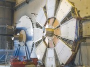 The first Small Wheel is finished in October 2007. Slide show of the photos. |
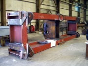 Visit to the TEMKA company in November 2007. Slide show of the photos. |
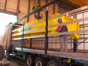 The JD liftingbeam arrives at CERN in November 2007. Slide show of the photos. |
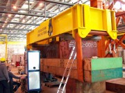 Loadtesting of the JD liftingbeam to 220 tonnes in November 2007. Slide show of the photos. |
The mobile crane is tried out in the JD assembly hall. |
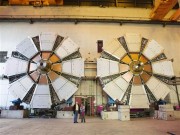 Both SWs are finished in January 2008. Slide show of the photos. |
Load testing of the first installation frame. |
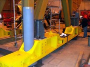 Installation of the lifting jacks on the installation frame. Slide show of the photos. |
Loadtesting of the lifting jacks on the first installation frame. |
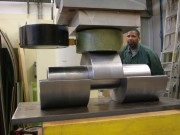 Load testing of the lifting pins for the installation frame. Slide show of the photos. |
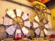 The installation frame is installed on the JD/SW. Slide show of the photos. |
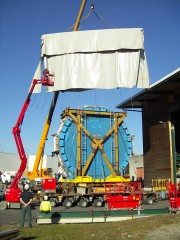 Transport of the first JD/SW to ATLAS. Slide show of the photos. Video |
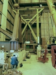 Load testing of the second installation frame. Slide show of the photos. |
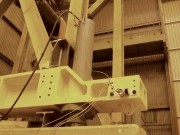 Loadtesting of the lifting jacks on the second installation frame. Slide show of the photos. |
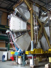 The JD/SW is rotated in the ATLAS surface building. Slide show of the photos. |
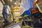 Preparation for transport in February 2008. Slide show of the photos. |
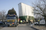 Transport of the second JD/SW to ATLAS. Slide show of the photos. |
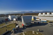 JD/SW transport in February 2008. Slide show of the photos. Video |
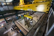 JD/SW-C installation in SX1 in February 2008. Slide show of the photos. |
|
Installation the first JD/SW on side C in ATLAS. |
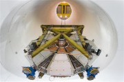 JD/SW-C installation in the ATLAS cavern in February 2008. Slide show of the photos. Video |
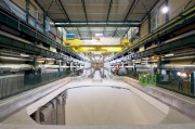 JD/SW-A installation in SX1 in February 2008. Slide show of the photos. |
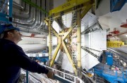 JD/SW-A installation in the ATLAS cavern in February 2008. Slide show of the photos. |
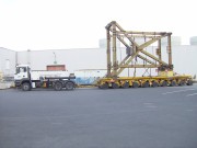 Transport back of the installation frames to building 191. Slide show of the photos. |
|||
 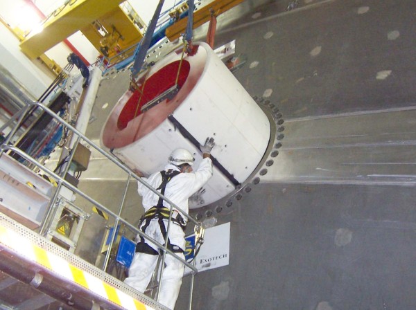 |
|||
 Photos taken of the JT rings at the Resarm factory in Belgium in September 2004: Slide show of the photos. |
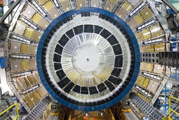
 Photos taken at CERN after the delivery from the Resarm company of the polyethylene ring for the JTV shielding. Slide show of the photos. |
Photos taken at CERN after the delivery from the Resarm company of the polyethylene petals for
the JTV shielding. |
 Photos taken at CERN after the delivery of the first JTT brass ring from Armenia in January 2005. Slide show of the photos. |
 The JTT polyboron cladding after it has been delivered by the Resarm company in June of 2005. Slide show of the photos. |
 The JTT installation platform in March 2006. Slide show of the photos. |
 The manufacture of the JTT plug in Skoda in April 2006. Slide show of the photos. |
 The manufacture of the JTT plug in Skoda in June 2006. Slide show of the photos. |
 The manufacture of the JTT plug in Skoda in June 2006. Slide show of the photos. |
 The installation of the JTV petals on the toroid in August 2006. Slide show of the photos. |
 The first set of JTT plugs after their arrival at CERN in September 2006. Slide show of the photos. |
 The second set of JTT plugs at Skoda in October 2006. Slide show of the photos. |
 The second set JTT plugs are stored in the UA1 pit in December 2006. Slide show of the photos. |
 The installation of the JTV ring in July 2007. Slide show of the photos. |
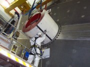 The JTT is installed in ATLAS in the summer of 2007. Slide show of the photos. |
 The VT beampipe. Slide show of the photos. |
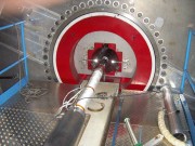 The JTT and the support of the VT beampipe. Slide show of the photos. |
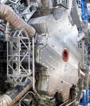 The JTT after installation in the Endcap Toroid. Slide show of the photos. |
||
  |
|||
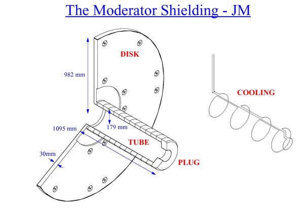
 Photos taken of the JM disk at the Resarm factory in Belgium in September 2004. Slide show of the photos. |
Photos taken at CERN after the delivery from the Resarm company of the polyethylene disk for
the JM shielding. |
 Photos taken in Prague during the manufacturing of the JM aluminium cover. Slide show of the photos. |
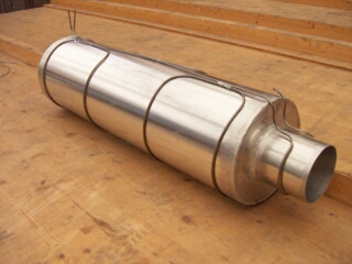 Photos taken at CERN after the delivery from CTU in March 2005 of the JM cover. Slide show of the photos. |
 Photos taken at CERN after the delivery from the Resarm company of the polyethylene tube for the JM shielding. Slide show of the photos. |
The JM shielding after installation in ATLAS in April 2006. |
 The JM shielding during the calorimeter installation. Slide show of the photos. |
 The JM shielding after the final installation in June 2006. Slide show of the photos. |
 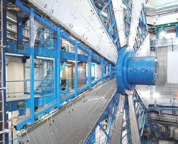 |
|||
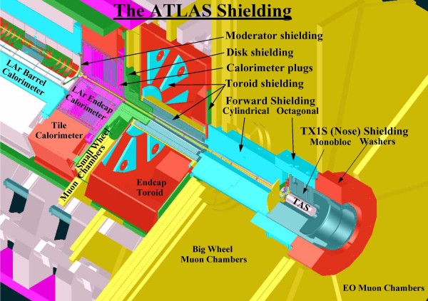
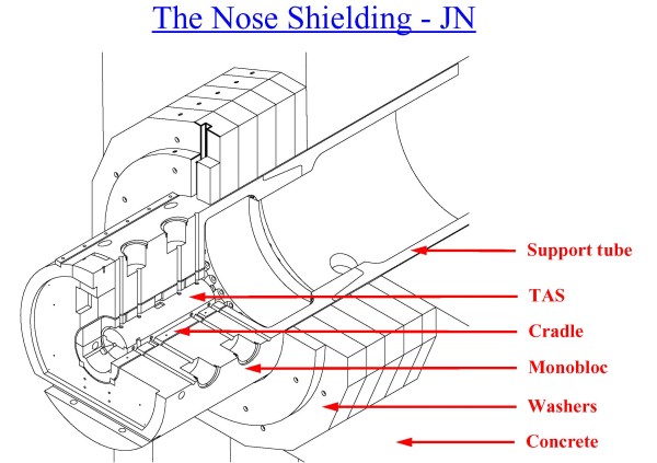
 Photos of various parts of the JN nose shielding (TX1S). Slide show of the photos. |
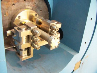 Photos of the JN monobloc and the TAS taken in June 2005. Slide show of the photos. |
 Installation of the JN monobloc in November 2006. Slide show of the photos. |
 Installation of JN washers in August 2007. Slide show of the photos. |
|
|||
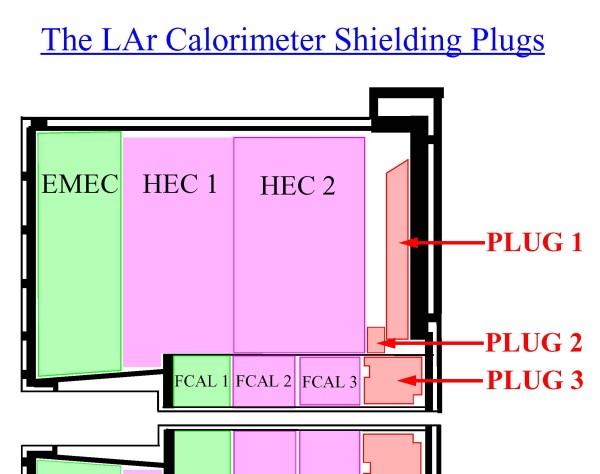
 Photos taken of the copper shielding plugs designed by Arizona and made in Australia for the endcap liquid argon calorimeters. Slide show of the photos. |
|||
|
|||
 Photos taken in October 2003 at a test of the flammability of polyetylhene and wax doped with boron or lithium. Slide show of the photos. |
 Photos taken in February 2004 at a test of the flammability of polyetylhene that is protected by special intumescent paint. Slide show of the photos. Quick Time Video of a test of painted cardboard (53 Mbyte) |
 Photos taken in July 2003 after a test of the radiation hardness of doped polyethylene in a reactor in Slovenia. Slide show of the photos. |
 Photos taken in January 2004 after a test of the radiation hardness of doped polyethylene in a reactor in Slovenia. Comparisons were made between high and low neutron fluxes. Slide show of the photos. |
 Photos taken in November 2004 after a test of the radiation hardness of intumescent paint in a reactor in the Czech republic. Slide show of the photos. |
|||
Back to the ATLAS home page
Back to the ATLAS shielding page
Responsible for the content of this page is
Vincent Hedberg
Last update:
1 December 2008