 The ATLAS Shielding Project
INDEX
Spain: Nortemecanica S.A
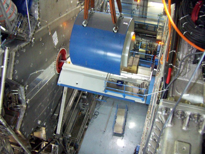
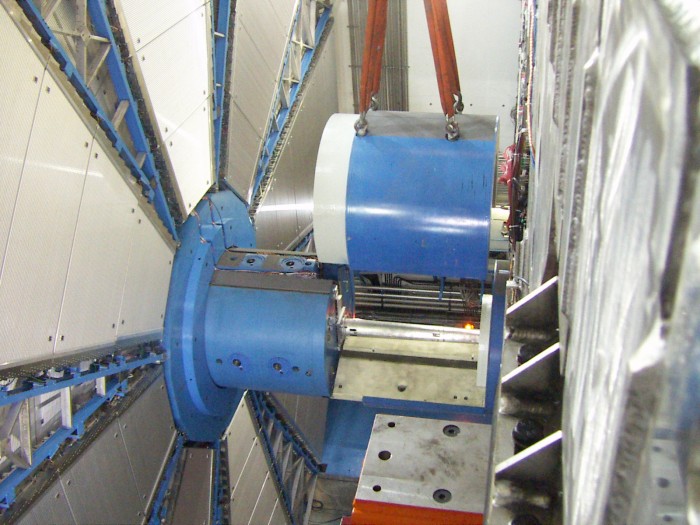
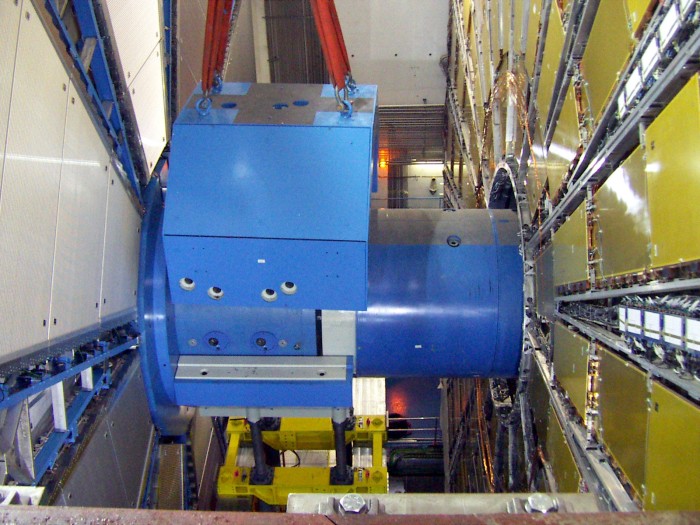
JFC1: 84 tonnes - 580 x 267 x 134 cm The JF Installation Installation plots by J. Palla. Click on a figure to get a high-resolution plot.
The JD/SW Installation
The JTV shielding consist of the
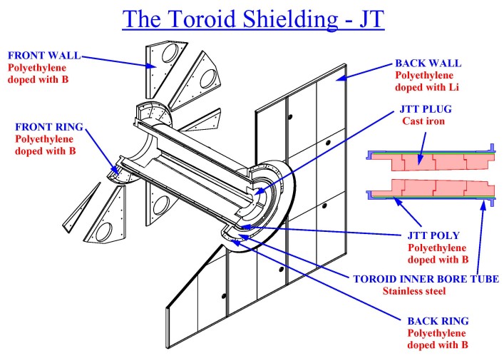
front wall (the "petals") made up of 8cm thick plates of polyethylene (Fig. 27)
doped with 5% (by weight) of boron carbide (B4C). These plates makes the
pattern on the ECT cryostat endplate that is shown in Figures 28 and 29. The outer
radius of the pattern is 347 cm.
Ideally the whole endplate should be covered by the shielding
but that is not possible due to a lack of space for it. Each of the two walls consist
of 16 different plates with a total weight of 924 kg.
In addition
to the front wall there is a front and back ring of doped polyethylene
as shown in the Figure above and in the Figures 30 and 31. The front
ring covers the radius 93 to 142 cm and it has a weight of 432 kg.
The back ring covers the radius 96.5 to 134.3 cm and has a weight of
220 kg.
A back wall made of 8 cm thick polyethylene has been
forseen as an upgrade project. It will be placed on the outside of the
cryostat between the ECT and the Big Muon Wheel. It will have to be
doped with lithium which produces less photons than boron since it
will not be possible to put up a photon filter in this region.
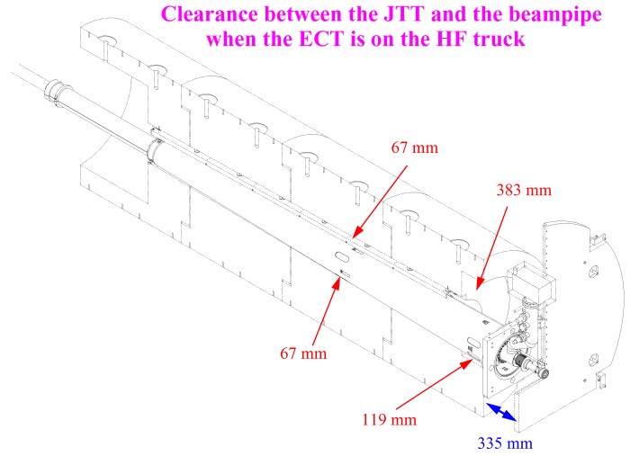
The JTT shielding is a cylindrical structure made of
ductile cast iron
that surrounds the beampipe in the endcap toroids (Fig. 32). The shielding
consists of four pieces called plug pieces, numbered 1 to 4 from the back (Fig. 34).
The front piece (plug 4) has a large hole in the center into which
the JD shielding will stick in. On the outside of the cast iron
is a polyethylene layer (Fig. 35) doped with B2O3 (5% by weight) which acts
as neutron shielding. The photons created in the polyethylene layer
are stopped by the stainless steel ECT bore tube that supports the
shielding.
The JTT shielding consist of 2x55=110 tonnes of cast iron
and 2x1.3=2.6 tonnes of polyethylene for a total weight of 113 tonnes.
The weight and size of the cast iron pieces are as follows:
PLUG 1: 13.2 tonnes - 118 x 160 x 160 cm
There are two parts:
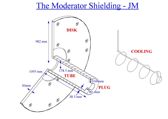
Both the disc and the tube/plug are covered by a 2 mm thick aluminium cover with a weight
of 5 kg and 21 kg respectively (Fig. 38 and 40).
The tube cover has water pipes on the inside for cooling during beampipe bake-out.
These cooling pipes are clearly seen in Figure 40. The shielding after installation
is shown as the black disc in Figure 41.
The disc was originally 50mm thick but the outer
20mm has been replaced by a layer of plastic scintillators thus reducing
the thickness to 30mm. Figure 42 shows three sectors of scintillators after
installation on the JM. The polyethylene is a fire hazard and the aluminium covers have
therefore been painted with a special white intumescent paint. This can be seen
in Figures 43 and 44 which shows the shielding after the covers have been installed
and painted.
Assembly drawings
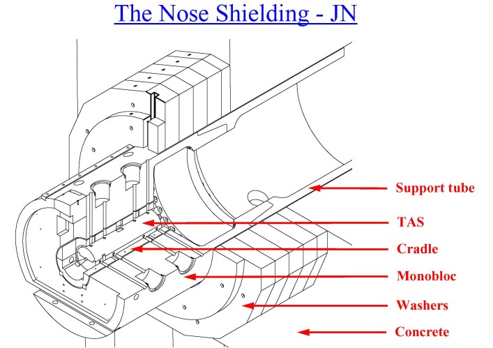
The main part of this shielding is the cylindrical 117 tonne heavy monobloc
(Fig. 48) that has an outer diameter of 295 cm. It is made of cast iron and it is
supported by a tube (Fig. 45) that is anchored in a 460 tonne concrete structure.
This cast iron tube has a weight of 51 tonnes and it has an inner diameter
of 257 cm and an outer diameter of 297 cm.
The 2x199 tonne heavy washers (Fig. 46) surrounds the tube and the monobloc.
They form a 201 cm thick structure in the beam direction.
There are six cast iron washers with washer no. 6 closest to the interaction point
and washer 1 attached to the concrete wall (Fig. 47). The inner diameter of
all washers are 301 cm. Washer 6 has a circular shape and the others are
16-sided to facilitate a future upgrade by adding cladding. The dimensions of the
washers are as follows:
The monobloc is bolted to the tube (Fig. 51). It has a 92.7 cm diameter hole
in the center for the TAS collimator (Fig 49.) and its cradle (Fig. 50).
The iron cradle (ID: 57.2 cm, OD: 87.2 cm and Weight: 5 tonnes) supports
the TAS and can be positioned with respect to the monobloc. The TAS is made
of copper, it is 180 cm long, has an outer diameter of 50 cm and an inner
diameter that is 3.4 cm. The weight of the TAS is about 3 tonnes.
Assembly drawings
There is a smaller
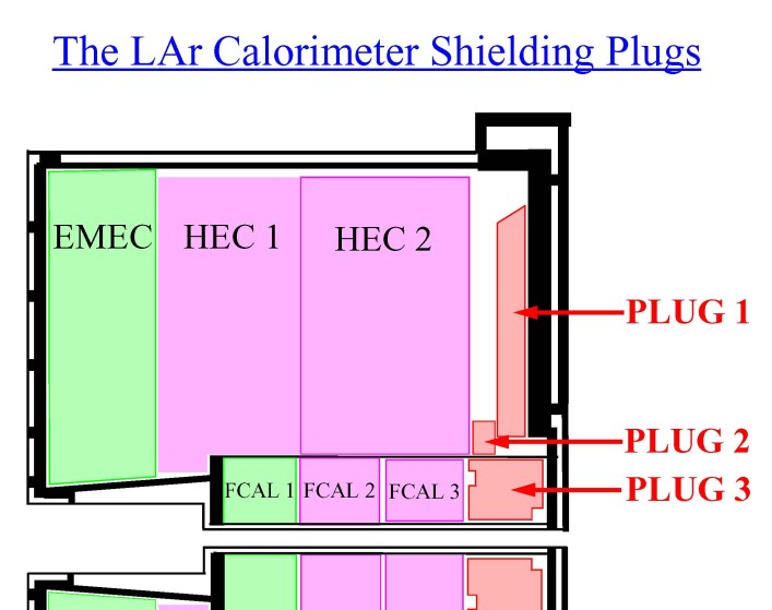
ring shaped shielding called Plug 2 with a weight of 0.9 tonnes, an inner diameter
of 95 cm and an outer diameter of 135 cm (Fig 53).
Plug 3 sits at the back of the forward calorimeter as shown in Figure 54. It has
an inner diameter of 19 cm, an outer diameter of 90 cm and a weight of 3 tonnes.
Drawing of the LAr endcap calorimeter
The total weight of the shielding is 2825 tonnes. The table below shows how the mass (in tonne)
is distributed among the different shielding parts. In addition, there has been
support and tooling structures made with a total weight of 62 tonnes (JD Rotation frames - 4.2 tonnes,
JD Lifting frames - 36 tonnes, JF A-frames - 4.6 tonnes, JF lifting tables - 17 tonnes).
The last row in the table above shows reduction in tonnes of material due to final shielding design compared to
the one in the TDR.
The pump in the VA beampipe
The connection between the VJ and the TAS beampipes
Hole in the shielding for the beampipe
JM Item Material Radius Z Thickness JM Disk lower
radius PE with 5% B4C 13.8-35 cm 351-352 cm 1 cm in z JM Disk upper
radius PE with 5% B4C 35-98.2 cm 351-354 cm 3 cm in z JM Tube PE with 5% B4C 14-17.85 cm 352-449.9 cm 3.85 cm in r JM Plug PE with 5% B4C 7.45-17.85 cm 449.9-457.9 cm 8 cm in z JM Disk cover Al 12.7-98.9 cm 350.8-351.0 cm 2 mm JM Plug cover
front Al 13.1-13.3 cm 352.0 444.2 cm 2 mm JM Plug cover
back Al 6.5-6.7 cm 444.2-457.7 cm 2 mm
LAr calorimeter - JD
JD Item Material Z Radius Thickness JD Disk - small Grey
steel 677.9-682.9 cm 75-270 cm 5 cm in z JD Disk - large Grey
steel 682.9-690.9
cm 54 436
cm 8 cm in z JD Tube Stainless
steel 678.4-888.9
cm 43-53
cm 10
cm in r JD Plug - front Brass
678.4
cm 13-42
cm 29
cm in r JD Plug - back Brass 886.4
cm 16.9-42
cm 25.1
cm in r JD Hub - front Brass 716.9
cm 54-76.41
cm 22.41
cm in r JD Hub - back Brass 786.9
cm 54-85
cm 31
cm in r JD Hub cladding PE + 5% B2O3
+ Pb 7
cm + 3 cm JD Cone cladding PE + 5% B2O3
+ Pb 5
cm + 3 cm
JD - JTT
JT Item Material Z Radius Thickness JTT Plug JD hole Ductile
iron 811.4 890.9
cm 60.0-80.2
cm 20.2
cm in r JTT Plug VT
hole Ductile
iron 890.9
cm 17.1-80.2
cm 63.1
cm in r JTT Plug VT hole Ductile
iron 1258.5
cm 24.2-80.2
cm 56.0
cm in r JTT Plug JF
hole Ductile
iron 1258.5-1285.0
cm 56.25-80.2
cm 23.95
cm in r JTT poly PE
+ 5% B2O3 818.1-1285.0
cm 80.2-85.7
cm 5.5
cm in r Toroid bore tube Stainless
steel 792.9-1288.2
cm 87.25-91.25
cm 4.0
cm in r JTV Front Ring PE
+ 5% B4C 805.9-821.9
cm 93-142
cm 16 cm in z, 49 cm in r JTV Back Ring PE
+ 5% B4C 1261.7-1275.7
cm 96.5-134.3
cm 8 cm in z, 37.8 cm in r JTV Front wall PE
+ 5% B4C 799.9-807.9
cm ca
145-345 cm 8 cm in z, 200 cm in r JTV Back Wall PE
+ 2.7 % Li 1288.2-1296.2
cm 160-350
cm 8 cm in z, 190 cm in r
JTT - JF
JF Item Material Z (cm) Inner Radius Outer Radius Thickness A frame Stainless
steel 1294.9-1319.9 Bridge - front Ductile
iron 1296.9
cm 26.7
cm 147
cm 119.1
cm in r Bridge - back Ductile
iron 1857.0
cm 30.8
cm 147
cm 111.4
cm in r Bridge back ledge Ductile
iron 1857.0-1877.0 43.8
cm 58.8
cm 15.0
cm in r Bridge cladding PE
+ 5%H3BO3 + Fe 1296.9-1796.0 147.4
cm 155
cm 4.6
cm + 3 cm JFC2 front nose Ductile
iron 1271.9-1296.9 28.0
cm 147
cm 121
cm r, 25 cm z JFC2 front Ductile
iron 1296.9
cm 28.2
cm 147
cm 118.8
cm in r JFC2 back Ductile
iron 1559.9
cm 30.2
cm 147
cm 116.8
cm in r JFC2 back nose Ductile
iron 1559.9-1579.9 30.3
cm 85
cm 54.7
cm r, 20cm z JFC2 cladding PE
+ 5%H3BO3 + Fe 1296.9-1559.9 147.4
cm 155
cm 4.6
cm + 3 cm JFC3 front bore Ductile
iron 1559.9-1579.9 89.0
cm 147
cm 58
cm r, 20 cm z JFC3 VJ hole Ductile
iron
1579.9 cm 30.4
cm 147
cm 116.6
cm in r JFC3 - back Ductile
iron 1853.0
cm 35.6
cm 147
cm 111.4
cm in r JFC 3 cladding PE
+ 5%H3BO3 + Fe 1559.9-1796.0 147.4
cm 155
cm 4.6
cm + 3 cm Octagonals Ductile
iron 1810-2099
cm 150.0
cm 199
cm 49
cm in r front cladding PE
+ 5%B2O3 + Fe 1799-1810
cm 150.0
cm 210
cm 8
cm + 3 cm in z side cladding PE + 5%H3BO3 + Fe 1810-2099 cm 199 cm 210
cm 8
cm + 3 cm in r
JF - JN
JN Item Material Z Radius Thickness TAS Copper 1903-2083
cm 3-25
cm 22.5
cm in r Cradle Ductile
iron 1867-2087.5
cm 28.6-43.6
cm 15
cm in r Monobloc front Ductile
iron 1861-2089.5
cm 46.35-147.5 101.15 cm in r, 228.5 cm in z Monobloc middle Ductile
iron 2089.5-2196.5
cm 128.5-147.5
cm 19
cm in r Monobloc back Ductile
iron 2196.5-2205.5
cm 108.5-147.5
cm 39
cm in r Monobloc + Tube Ductile
iron 2205.5-2286.5
cm 108.5-148.5
cm 40
cm in r Tube front Ductile
iron 2286.5-2306.5
cm 108.5-148.5
cm 40
cm in r Tube back Ductile
iron 2306.5-2605.5
cm 128.5
-148.5 cm 20
cm in r Washers -
front Ductile
iron 2099.1-2119.1
cm 150.5-207.5
cm 57 cm in r, 20 cm in z Washers - back Ductile
iron 2119.1-2300
cm 150.5-262
cm 111.5 cm in r, 180.9 cm in z Concrete -
left Concrete 2300-2640
cm 148.5-422
cm 273.5 cm in r, 340 cm in z Concrete -
right Concrete 2300-2580 cm 148.5-422 cm 273.5 cm in r, 280 cm in z
The old shielding web-pages are available here.
Responsible for the content of this page is
Vincent Hedberg
Contact persons for JM, JD, JT and JF: Vincent Hedberg (Project Leader)
and Jan Palla (Project Engineer)
Contact person for JN: Francois Butin
Contact person for LAr plugs: Leif Shaver
Institutes
Suppliers
Introduction
Shielding elements
JF - The forward shielding
JD - The disk shielding
JT - The toroid shielding
JM - The moderator shielding
JN - The nose shielding
Plugs in the LAr calorimeter
Cladding
Materials
Positions and dimensions
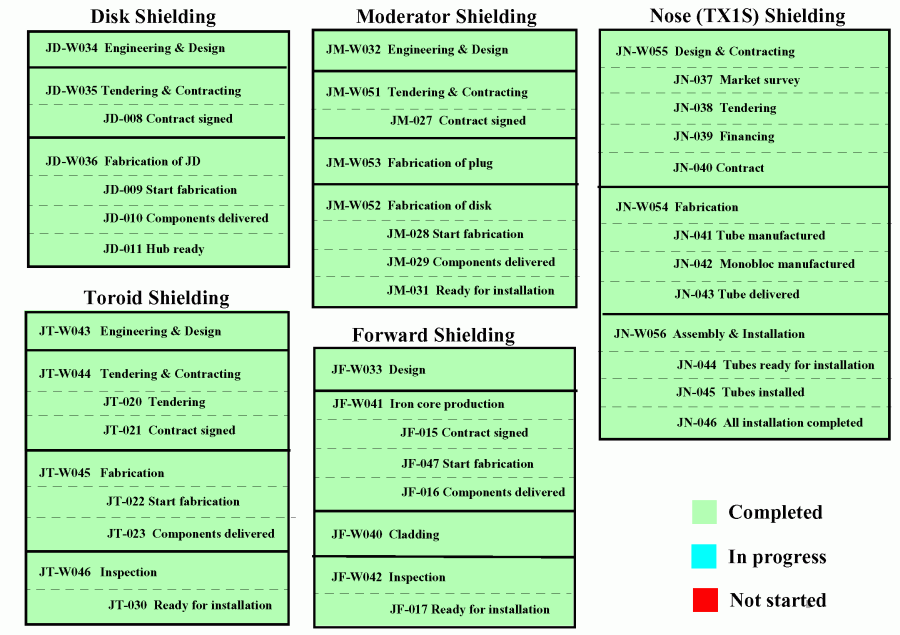
Status
Workpackages
INSTITUTES PARTICIPATING IN THE PROJECT
CERN (Switzerland)
Yerevan Physics Institute (Armenia)
Institute of Physics, University of Belgrade (Serbia)
Institute of Experimental and Applied Physics, Czech Technical University in Prague (The Czech Republic)
Institute of Particle and Nuclear Physics, Charles University in Prague (The Czech republic)
Department of Experimental High-Energy Physics, Lund University (Sweden)
Department of Physics, University of Arizona (USA)
People
SUPPLIERS TO THE ATLAS SHIELDING PROJECTS
Bulgaria: Heavy Machinebuilding
Germany: Hunger Hydraulik
& Siempelkamp
Italy: SIMIC S.p.A.
The Slovak Republic: JAMP sro & Slovmetal sro
Serbia: LOLA SISTEM & Kryoprema
Armenia: Energocomplex
The Czech republic:
Tranza AS &
Skoda Hute sro &
Kopos Kolin AS &
FEST Ostrava sro &
RADL sro &
Stampa Ostrava sro
Switzerland:
AGI AG Zurich &
Mantrade Fordertechnik AG &
Bossard &
Bachofen AG &
Spanset SA &
Matec Soudure Sarl &
ARSA Aciers Romands SA &
Bischof SA &
Friderici SA &
AMC Technologies SA &
Bruetsch/Ruegger AG
France:
Farba Sarl &
Gonzales SA &
Roger Colin SAS &
SCMR &
STAS Sarl &
Pivicat SA &
SAMSE &
SVH &
BVM Sarl &
A2S
Pakistan: Heavy Mechanical Complex 3 (HMC3)
Australia: VEEM Engineering
Belgium: Resarm SA
Greece: TEMKA SA
INTRODUCTION
The very high energy and collision rate at the LHC means that the levels of low-energy neutron,
high-energy hadron and photon radiation are at an extremely high level in the ATLAS experiment.
This causes several problems such as radiation damage to detectors and electronics and background
signals resulting in enhanced trigger rates in some of the detector systems such as the muon detector.
The high radiation levels also cause
activation of certain detector elements
with the result that some maintenance
operations will become difficult due to radioprotection considerations.
The main problem is not caused by the particles originating from the interactions but from secondary
particles created in hadronic showers in the beampipe, forward calorimeter and the TAS collimator.
The purpose of the shielding in ATLAS is to reduce the number of background particles in the Inner
Detector and the Muon spectrometer to a manageable level and to
protect people working in the electronics cavern (USA15).
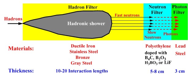
Since different types of radiation
require different types of shielding materials, a multi-layered shielding approach is used in ATLAS.
The inner layer has as a purpose to stop high energy hadrons and its secondaries. This layer is made
of material which gives a large number of interaction lengths such as iron or copper.
In the case of iron, studies have shown that a minimum carbon content of a couple of percent is
advantageous since it moderates the neutron energy down to lower values. A second layer,
consisting of doped polyethylene, is used to moderate the neutron radiation escaping from
the first layer and the low energy neutrons are then captured by a dopant (either boron or lithium).
Photon radiation is created in the neutron capture process and these photons are stopped in the
third shielding layer which consists of steel or lead. Lead is more effective in stopping photons
but it has the disadvantage of giving off more neutron radiation than steel.
The shielding physics is discussed further in
chapter 2 of the
ATLAS Radiation Taskforce Report.
Massive simulations have been carried out by the
ATLAS Radiation Task Force
during several years in order to optimize the effectiveness
of the shielding in ATLAS. This optimization process is discussed in
chapter 8
of the
Radiation Taskforce Report. Tables with more detailed results are presented
on a separate
web site.
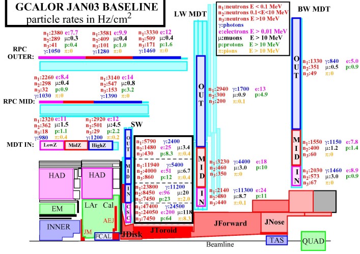
The background radiation that
can be expected with the shielding has been calculated and is shown in the Figure above.
More detailed tables and plots are available on a separate
web site.
DESCRIPTION OF THE SHIELDING ELEMENTS

The shielding in ATLAS is divided up in the six subprojects that are illustrated in the figure
above. The drawings of the shielding elements are all on
CDD. In order to find the folders with
only the latest up-to-date drawings select the "Folders" option in CDD and then enter the search
terms JF%, JD%, JM%, JN% or JT%. This will give lists of folder with only up-to-date drawings.
The subproject are described below.
The ATLAS shielding is described in the large ATLAS detector paper
2008 JINST3 S08003.
The status of the shielding project at the end of 2008 is described in the EDMS document
ATL-J-EN-0008.
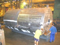
Fig 1. The ductile cast iron pieces for the core part.
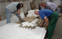
Fig 2. Polyethylene bricks are being assembled for the cladding.

Fig 3. The outer steel plates after manufacturing.

Fig 4. The bridge section arrives at CERN.
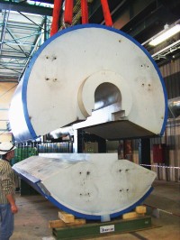
Fig 5. JFC1 and JFC2.
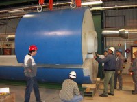
Fig 6. The core part is being assembled at CERN.

Fig 7. One of the octagonal upper pieces arrives at CERN.
The purpose of the two Forward Shielding assemblies (JF) is to protect the big muon wheel and the muon
EO chambers from background particles created in secondary interactions in the beampipe,
the calorimeters and the TAS collimators. This shielding is removable and will be stored
in the surface building during maintenance of ATLAS. The shielding consists of two parts:
The cylindrical core and the octagonal back. Three pieces called JFC1 ("the bridge"),
JFC2 and JFC3 are used for the core and two pieces called "JFS3 upper" and "JFS3 lower"
for the octagonal back.
All pieces are made of
cast ductile iron
(Fig. 1) surrounded by a layer of polyethylene doped
with boron followed by a 3 cm thick steel layer (Fig. 3). The ductile iron has a large carbon
content and the carbon acts as a moderator of the neutron radiation. The core pieces have
a 5 cm thick polyethylene layer and an 8 cm thick layer is surrounding the
octagonal pieces. These polyethylene layers are made of 10,000
bricks
(Fig. 2) with
three different shapes. The polyethylene is rich on hydrogen which will slow down (moderate)
the neutrons. The polyethylene also contains 5% of boron by weight in the form of H3BO3.
This boron has a large absorption cross section for thermal neutrons.
The outermost steel layer stops the photons created when the neutron radiation is
absorbed by the boron.
The bridge section is supported at the front by the stainless steel A-frame with
a weight of 2.3 tonnes and at the back by a ledge in the JN monobloc (Fig. 51).
The A-frame was load tested in Serbia to 173 tonnes before delivery. After modifications at CERN,
it was re-tested to 189 tonnes (Fig. 12) on the 15th of April 2008. The deformation of both A-frames
was 11 mm.
JFC2 and JFC3 are supported by the bridge section. The total
weight carried by the A-frame and the ledge in the monobloc is 275 tonnes. Figure 11
shows how the lower octagonal piece is supported by a 8.5 tonnes heavy hydraulic lifting table
(Fig. 10) that is positioned on top of the HF truck. The upper octagonal pieces rest on the
lower piece. The weight
of the two octagonal pieces is 143 tonnes. The stroke of the jacks (Fig. 13) in the lifting table is
130 cm and each jack can lift 120 tonnes i.e. the lifting table is designed to carry a
total weight of 480 tonnes (in case the monobloc cannot take the weight of the core
the lifting table is designed to take the weight of both the core and the octagonals).
The JF shielding consist of 2x387=775 tonnes of cast iron, 2x24=50 tonnes of steel plates
and 2x5.5=11 tonnes of polyethylene for a total weight of 2x418=836 tonnes.
The weight and size of the pieces are as follows:
JFC2: 93 tonnes - 308 x 310 x 232 cm
JFC3: 98 tonnes - 293 x 310 x 232 cm
JFS3U: 77 tonnes - 420 x 300 x 246 cm
JFS3L: 66 tonnes - 420 x 300 x 212 cm
Assembly drawings
Drawings of the large cast iron pieces
Drawings of the polyethylene layer
Drawings of the steel plates
Drawings of the A-frame
Drawings of the lifting table
Technical Specifications
FEA calculation reports and SC approvals
Webcam of forward shielding on side A in ATLAS
Webcam of forward shielding on side C in ATLAS
More JF photos
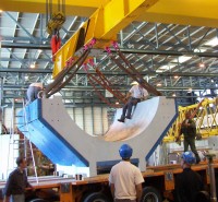
Fig 8. A lower octagonal piece is being unloaded.

Fig 9. The octagonal pieces after assembly.

Fig 10. The JF lifting table with its 4 hydraulic jacks in grey.
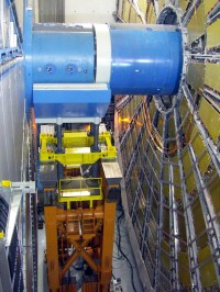
Fig 11. The lifting table when it supports the lower octagonal piece.
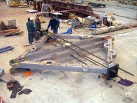 Fig 12. The A-frame is being load tested.
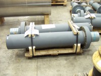
Fig 13. The hydraulic lifting jacks for the JF lifting table.
Installation Manager: Raphael Vuillermet
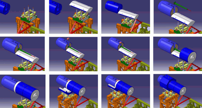
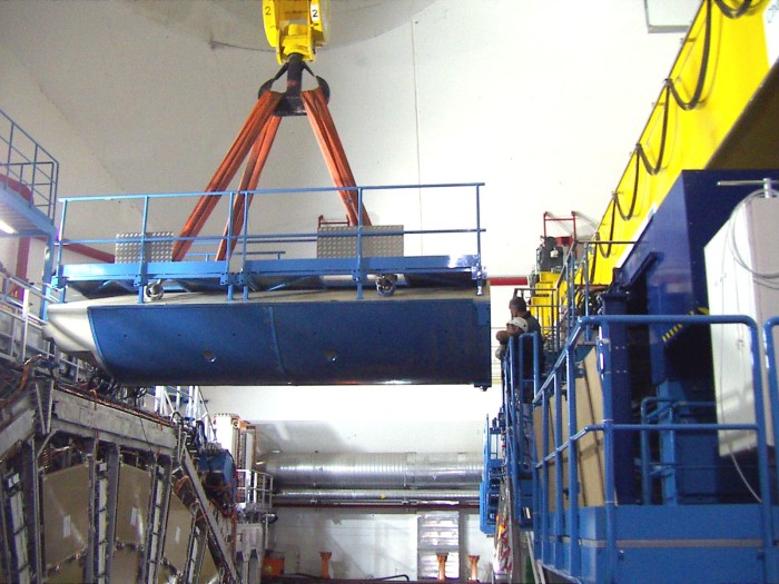
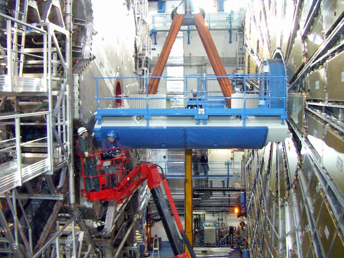

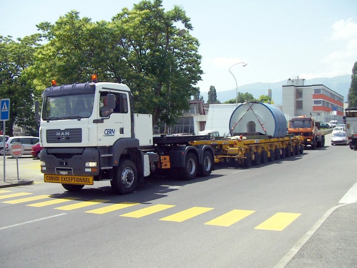

Report ATL-JF-IP-0001:
Installation of the forward shielding - V. Hedberg
TMB presentation - 13 March 2008:
JF Shielding Modifications and Installation - R. Vuillermet & D. Mladenov
ATLAS week presentation - 7 April 2008:
Installation of the forward shielding and LUCID
(Video) - V. Hedberg
Magnet workshop - 15 April 2008:
Forces between magnets and shielding - W. Kozanecki
Magnetic field meeting - 30 April 2008:
Forces between magnets and shielding during installation - A. Vorozhtsov
PPSPS - 22 May 2008: Installation of the JF shielding - P. Petit
Report ATL-HT-OP-0008 - 26 September 2008: Procedure for the installation of the Forward Shielding - P. Petit
Report ATL-HT-OP-0009 - 26 September 2008: Procedure for the dismantling of the Forward Shielding - P. Petit
Action lists from the JF installation meetings (by R. Vuillermet):
24 January 2008 -
30 January 2008 -
7 February 2008 -
14 February 2008 -
21 February 2008 -
28 February 2008 -
6 March 2008 -
13 March 2008 -
20 March 2008 -
3 April 2008 -
10 April 2008 -
16 April 2008 -
29 April 2008 .
Installation of JFC1 on side C -
Photos
Video
Installation of JFC1 on side A -
Photos
Installation of JFC2 on side C -
Photos
Video
Installation of JFC2 on side A -
Photos
Installation of JFC3 on side C -
Photos
Video
Installation of JFC3 on side A -
Photos
Removal of JFC1 using the lifting table -
Photos
Video
Installation of JFS3 on side A -
Photos
Video
Installation of JFS3L on side C -
Photos
Video
Installation of JFS3U on side C -
Photos
Video

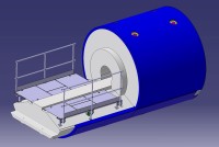
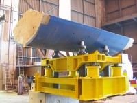

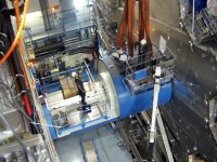

Fig 14. The disc pieces during manufacturing.
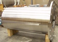
Fig 15. The stainless steel tube that supports the plug pieces.

Fig 16. One of the four plug pieces that sits in the tube.
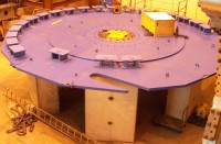
Fig 17. The ring segments are being assembled.
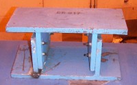
Fig 18. One of the ring segments.
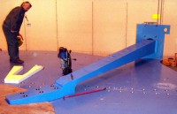
Fig 19. A rib piece is being attached.
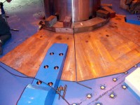
Fig 20. Installation of cone pieces.
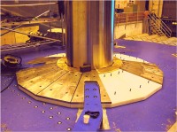
Fig 21. The polyethylene and lead cladding is attached to
the cone pieces.
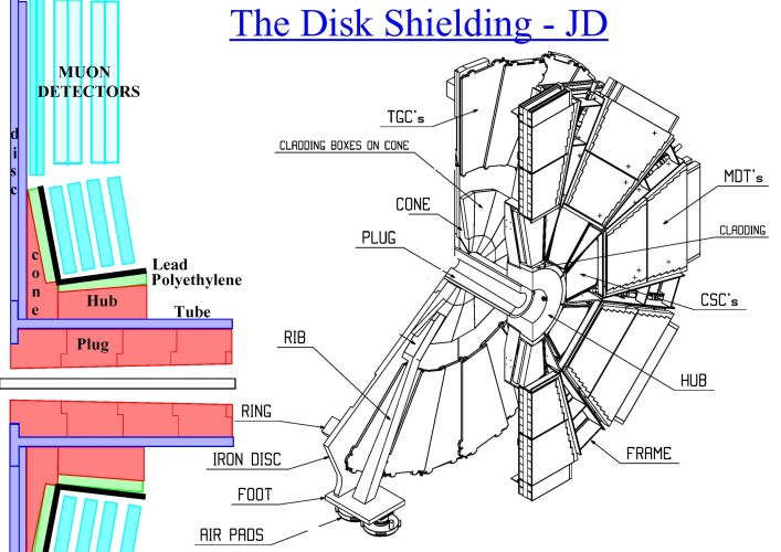
The Disk Shielding (JD) has a threefold purpose: It supports the muon
chambers in the first forward muon station (the Small Wheel), it shields
these chambers from radiation and it returns the magnetic field from the
solenoid magnet in a well defined way. The various parts of the disk shielding
are shown in the figure above. The largest pieces are the five plates
that make up the disc itself (Fig. 14). Three of these are used for the 8 cm thick
"large disc" with a diameter of 872 cm and two for the 5 cm thick "small disc"
which has a diameter of 540 cm. The two cast iron ribs (1.6 tonnes) that are attached to
the large disk are used to increase the mechanical stability of the JD (Fig. 19 & 25).
31 ring segments (Fig. 17 & 18) with a weight of 161 kg each are attached to the large disk.
The purpose of these
ring segments are to lead the magnetic field back through the electronic boxes
("the drawers") of the Tile calorimeter. One ring segment will cover
two Tilecal drawers. The size of the ring segments can be adjusted in the
z-direction from 270 to 340 mm.
A 208 cm long and 5.4 tonne heavy stainless steel tube (Fig. 15) with a diameter of 106 cm is
attached to the center of the large disc. It is filled with 4 brass plug
pieces (Fig. 16) with a total weight of 8.3 tonnes. All the leaded red brass pieces
(UNS C83600)
in the shielding of ATLAS consists of 85% Cu, 5% Pb, 5% Sn and 5% Zn.
The purpose of the plug is to shield the muon chambers from background
radiation created by interactions in the beampipe and forward calorimeter.
The brass cone pieces (Fig. 20) have the same purpose as the plug. They are covered
by a cladding consisting of a 70 mm thick polyethylene layer doped with 5% (by weight)
of B2O3 followed by a 30 mm thick lead layer
(UNS L52901)
(Fig. 21). The weight of one cone assembly
is 5.4 tonnes (brass) + 442 kg (polyethylene) + 2.1 tonnes (lead).
The 70 cm long hub piece (Fig. 22) is made of brass with a measured density
of 8.44+-0.04 g/cm3. It supports the Small Muon wheel
with its CSC and MDT chambers and it can slide on the tube with the help
of a rail system on the top. In this way the Small Wheel detectors can be serviced
from both sides. This also makes it possible to reach the TGC detectors that are
attached to the disc. The hub has a cladding consisting of a 5 cm thick B2O3 layer (Fig. 23)
and a 3 cm thick lead layer. The total weight of the hub (including cladding)
is 8.4 tonnes. Of this 133 kg comes from the polyethylene and 1.1 tonne from the lead.
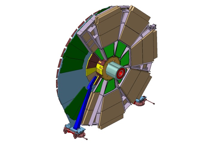
The finished JD shieldings (Fig. 24 & 25) have a diameter of 872 cm and a total
weight of 2x87=174 tonnes. The total weight of the muon chambers is about 13 tonnes
(SW 12 tonnes and TGCs 1 tonne) which
brings the total weight of one JD/SW assembly to 98 tonnes. The chambers also increase
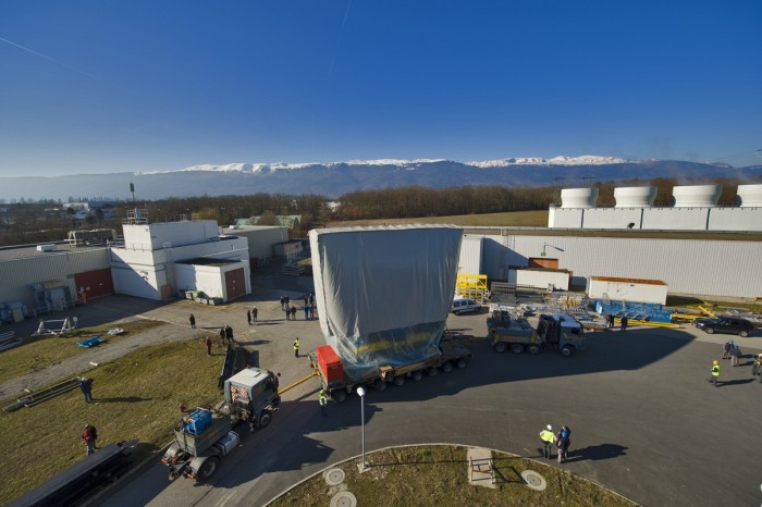
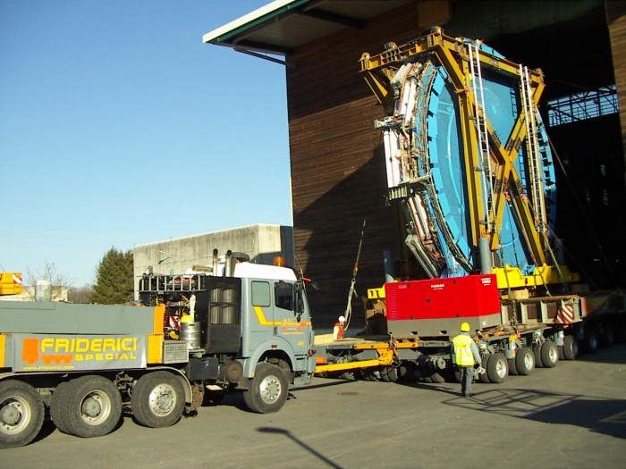
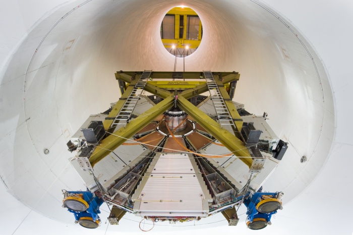
the diameter to 930 cm. A special installation frame (Fig. 26) has been build to
transport the JD/SW assembly. This frame has a weight of 18 tonnes and so the total
weight of JD + SW + Frame is 116 tonnes. If the JF hydraulic jacks are used in combination
with the lifting frame that will add another 17 tonnes for a total weight of 133 tonnes.
Assembly drawings
Drawings of the steel disk
Drawings of the stainless steel tube
Drawings of the brass plug
Drawings of the brass cone and the polyethylene & lead cladding
Drawings of the cast iron ribs
Drawings of the steel ring pieces
Drawings of the feet
Drawings of the brass hub and the polyethylene & lead cladding
Drawings of the installation frame
Drawings of the tooling for the rotation
Drawings of the hub movement system
Drawings of the JD lifting beam
Drawings of the load test beam
Drawings of building 191
Webcam in building 191
Technical Specifications
FEA calculation reports and SC approvals
Trench in SX1 - Engineering change request
Increased length of JD tube - Engineering change request
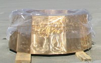
Fig 22. The hub piece that supports the Small Wheel.

Fig 23. Two of the polyetylene pieces used in the cladding on the hub.

Fig 24. The front of the JD shielding (the IP side).
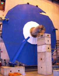
Fig 25. The back of the JD shielding.
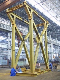
Fig 26. The lifting frame that is used to transport the JD/SW assembly.
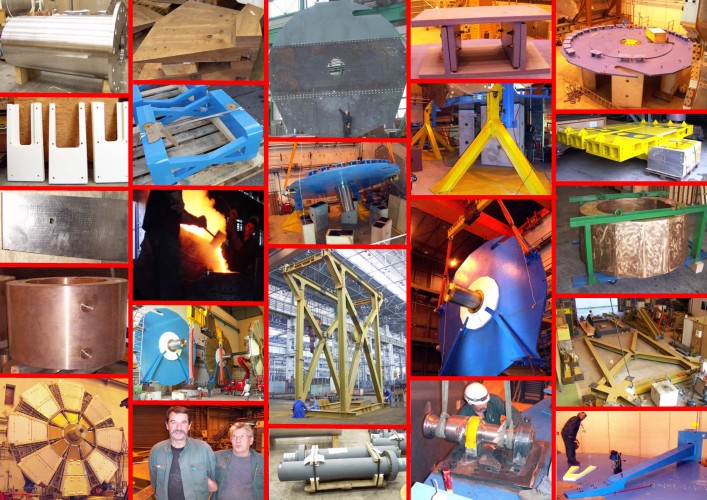
More JD photos
Installation Manager: Patrick Petit
Installation review on JD/Small Muon Wheel - 10 may 2006
Review of the installation of the small wheels - 8 October 2007
TMB presentation - 31 January 2008
JD/SW installation note
PPSPS notes for the JD/SW installation
Note describing the JD movement procedure on the rails
Dynamic conflict study: Report - Video (15 Mb in wmv-format)
Video of the closing of the small wheel on the JD.
(11Mb file in wmv-format)
Video of one of the loadtests of the JD installation frame.
(26Mb file in wmv-format)
Video of the first transport of the JD/SW to ATLAS.
(72Mb file in wmv-format)
Video of the installation of JD/SW-C in ATLAS.
(27Mb file in wmv-format)
The media event on the 29:th of February 2008.
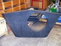
Fig 27. A JTV petal segment in the front wall.
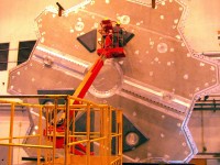
Fig 28. The JTV petals are being installed on the endcap toroid endplate.
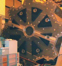
Fig 29. The endcap toroid endplate after installation of all petals.
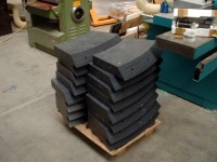 Fig 30. The pieces making up one of the JTV rings.

Fig 31. One of the two JTV rings.
The toroid shielding consists of two parts: JTT which surrounds
the beampipe and JTV which is neutron shielding situated inside
the endcap toroid cryostat. The purpose of the JTV shielding is
to moderate neutron radiation and then to stop the low-energy
neutrons by absorption in boron. The photons created in this process
are stopped by the ECT cryostat.
PLUG 2: 15.5 tonnes - 128 x 160 x 160 cm
PLUG 3: 15.5 tonnes - 128 x 160 x 160 cm
PLUG 4: 11.0 tonnes - 128 x 160 x 160 cm
The overall length of the JTT shielding is 473.6 cm (Fig.33).
The polyethylene layer is 55 mm thick i.e. the diameter of the
JTT after assembly is 171 cm (the diameter of the ECT bore tube is 174.5 cm
and its length is 495.3 cm).
Assembly drawings of the shielding around the beampipe (JTT)
Assembly drawings of the shielding inside the toroid vacuum vessel (JTV)
Drawings of the cast iron cylinder surrounding the beampipe
Drawings of the polyethylene cladding on the iron cylinder
Drawings of the polyethylene petals on side A
Drawings of the polyethylene petals on side C
Drawings of the polyethylene ring on the IP side
Drawings of the polyethylene ring on the non-IP side
Technical Specifications
FEA calculation reports and SC approvals
Change of brass to iron in JTT plug - Engineering change request
More JT photos
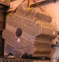
Fig 32. The ECT cryostat. The JTT is installed in the hole in the center.
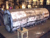
Fig 33. Test assembly of the JTT plug pieces.
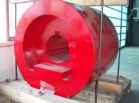
Fig 34. The final JTT ductile iron core pieces.

Fig 35. The JTT polyethylene cladding.

Fig 36. The JTT shielding while it was stored in the old UA1 shaft.

Fig 37. Half of one JM disc.

Fig 38. The aluminium cover for the disc.

Fig 39. The pieces for the JM plug.
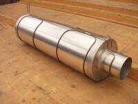 Fig 40. The aluminium cover and cooling pipes for the JM plug.
The moderator shielding (JM) on the front face of the endcap liquid argon calorimeters
protects the inner detector from back-splash
of neutrons from the calorimeter. It is made with a mass that is as small
as possible and the total weight of this shielding is only 2x168 kg.
The moderator shielding is made of polyethylene doped
with boron carbide (B4C). The carbon makes the polyethylene black in color
and very hard. This dopant also results in a plastic that is more radiation hard
than if other boron dopants were used. This is important since the shielding
in front of the forward calorimeter is exposed to a very large dose of radiation
during the ATLAS lifetime. The density of the doped polyethylene has been measured to
be 0.990+-0.001 g/cm3 at 23oC.
1) The 2m diameter disc on the front face of the endcap
liquid argon calorimeter with a weight of 90 kg (Fig. 37);
2) The tube and plug which lines the alcove in front
of the forward calorimeter with a weight of 52 kg (Fig. 39).
Drawings of the polyethylene parts
Drawings of the aluminium cover
Drawings of the cooling system
Description of the polyethylene shielding
Test of intumescent paint
Polyethylene Agreement On Safety
More JM photos
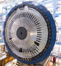
Fig 41. The JM after installation on the endcap calorimeter.

Fig 42. Installation of scintillators on top of the JM disc.

Fig 43. The finished JM has been installed on the calorimeter.
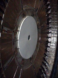
Fig 44. The aluminium cover is painted with a special white intumescent paint.
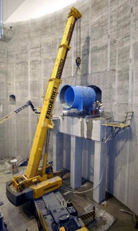
Fig 45. Installation of the support tube.

Fig 46. One of the washers.
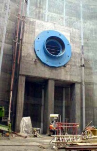
Fig 47. The tube and the first washer after installation.
The nose (JN) shielding, or the TX1S shielding as it is also called,
has as a purpose to support the TAS collimator and to protect ATLAS
from the radiation created in the TAS. The purpose of the TAS collimator
is to prevent the first LHC quadrupole from quenching due to the
heat created by the particles from the interactions in ATLAS. The nose
shielding is permanently installed in ATLAS and cannot as the forward
shielding be removed during shutdowns.
Washer 1. Outer diameter: 524cm, Thickness: 30.5 cm, Weight: 28 tonnes
Washer 2. Outer diameter: 524cm, Thickness: 37.6 cm, Weight: 40.5 tonnes
Washer 3. Outer diameter: 524cm, Thickness: 37.6 cm, Weight: 40.5 tonnes
Washer 4. Outer diameter: 524cm, Thickness: 37.6 cm, Weight: 40.5 tonnes
Washer 5. Outer diameter: 524cm, Thickness: 37.6 cm, Weight: 40.5 tonnes
Washer 6. Outer diameter: 415cm, Thickness: 20.0 cm, Weight: 9 tonnes
Drawings of the monobloc
Drawings of the support tube
Drawings of the cradle
Drawings of the washers
Drawing of the concrete support structure
Technical specifications and calculation reports
More JN photos

Fig 48. Front view of the monobloc and the cradle (lower right).
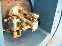
Fig 49. Front view of the TAS collimator and the remotely controlled
beampipe flange.

Fig 50. Back view of the TAS and the cradle.
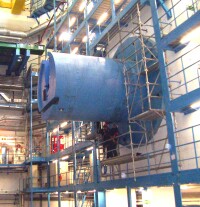
Fig 51. The monobloc after installation.
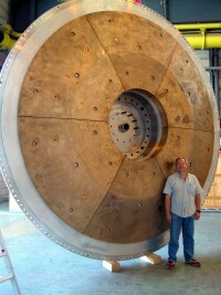
Fig 52. Plug 1.
There are three brass shieldings inside the endcap liquid argon cryostat.
The largest one (Plug 1) has an inner diameter that is 118.2 cm, an outer
diameter that is 386.8 cm and a weight of 12 tonnes (Fig. 52). It is attached
to the back endplate of the cryostat.
Drawing of the FCAL
Drawing of Plug 1
Drawings of Plug 2
Drawing of Plug 3
Technical specifications
More LAr plug photos
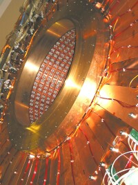
Fig 53. Plug 2.

Fig 54. The forward calorimeter with Plug 3 shown as the cylinder
to the right.
CLADDING
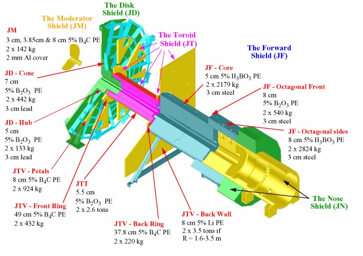
SUMMARY OF MATERIALS
JN-Nose Shielding:
JF-Forward Shielding:
JD-Disk Shielding:
JT-Toroid Shielding:
JM-Moderator Shielding:
Calorimeter Plugs:
Total:
Reduction in new design:
Concrete
920
-
-
-
-
-
920
0
Cast Iron
744
775
6.6
110
-
-
1636
224 (JN)
Grey Steel
-
50
107
-
-
-
157
492 (JF)
Stainless Steel
-
-
14
-
-
-
14
0
Brass
-
-
42
-
-
32
74
179 (JT)
Polyethylene
-
11
1.2
5.8
0.28
-
18
55 (JF & JT)
Lead
-
-
6.3
-
-
-
6
128 (JF)
POSITIONS AND DIMENSIONS
Beampipe drawings
Overview drawing of the ATLAS beampipe
The inner detector (VI) beampipe
The inner detector (VI) beampipe cladding

The LAr calorimeter (VA) beampipe
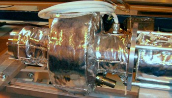
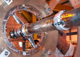
The LAr calorimeter (VA) beampipe cladding
The VA pump
The VA fixed support to the JD
The VA rolling support
The toroid (VT) beampipe

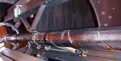
The toroid (VT) beampipe cladding
The VT fixed support to the JTT
The forward shielding (VJ) beampipe
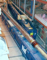
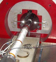
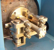
The forward shielding (VJ) beampipe cladding
The VJ support cone
TAS assembly drawing
The TAS beampipe
The pump in front of the TAS
The remote flange in front of the TAS
BEAMPIPE
VI
VI
VI
VA
VA
VA
VA
VA
VA
VA
VT
VT
VT
VT
VT
VT
VJ
VJ
VJ
VJ
VJ
VJ
VJ-TAS
TAS
TAS
TAS
Z POSITION
0-3550 mm
3550-3650 mm
3636-3650 mm
3650-3664 mm
3650-9000 mm
3786-3787 mm
3787-3843 mm
3843-3844 mm
3792-3838 mm
8986-9000 mm
9000-9014 mm
9000-10467 mm
10467 mm
10507 mm
10507-13207 mm
13187-13207 mm
13207-13227 mm
13207-14314 mm
14314 mm
14412 mm
14412-18499 mm
18477-18499 mm
18499-18980 mm
18980-19033 mm
19033-21110 mm
19033-20833 mm
RADIUS
29.0-29.8 mm (0.8 mm Be)
29.0-30.0 mm (1.0 mm Al)
30.0-43.0 mm (13 mm Al)
30.0-43.0 mm (13 mm SS)
29.2-30.0 mm (0.8 mm SS)
30.0-84.0 mm (54 mm SS)
83.0-84.0 mm (1 mm SS)
30.0-84.0 mm (54 mm SS)
48.0-71.0 mm (23 mm Ti)
30.0-43.0 mm (13 mm SS)
30.0-43.0 mm (13 mm SS)
29.2-30.0 mm (0.8 mm SS)
29.2-30.2 mm (1.0 mm SS)
40.0-41.0 mm (1.0 mm SS)
40.0-41.0 mm (1.0 mm SS)
41.0-76.0 mm (35 mm SS)
41.0-76.0 mm (35 mm SS)
40.0-41.0 mm (1.0 mm SS)
40.0-41.5 mm (1.5 mm SS)
60.0-61.5 mm (1.5 mm SS)
60.0-61.5 mm (1.5 mm SS)
61.5-101.0 mm (39.5 mm SS)
-
17-120 mm (103 mm SS)
17-30 mm (13 mm Cu)
30-250 mm (220 mm Cu)
ISOLATION JACKET
4.4 mm aerogel + heater
4.4 mm aerogel + heater
-
-
4.4 mm aerogel + heater
18 mm jacket
18 mm jacket
18 mm jacket
-
-
-
4.4 mm aerogel + heater
4.4 mm aerogel + heater
4.4 mm aerogel + heater
4.4 mm aerogel + heater
-
-
4.4 mm aerogel + heater
4.4 mm aerogel + heater
4.4 mm aerogel + heater
8.4 mm aerogel + heater
-
-
-
-
-
COMMENT
Be beampipe
Al beampipe
Al flange
SS flange
SS beampipe
SS Pump shell
SS Pump shell
SS Pump shell
Ti Pump element 350g
SS flange
SS flange
SS beampipe - front
SS cone - front
SS cone - back
SS beampipe - back
SS flange
SS flange
SS beampipe - front
SS cone - front
SS cone - back
SS beampipe - back
SS flange
See figure below
SS TAS flange
Cu beampipe
Cu collimator

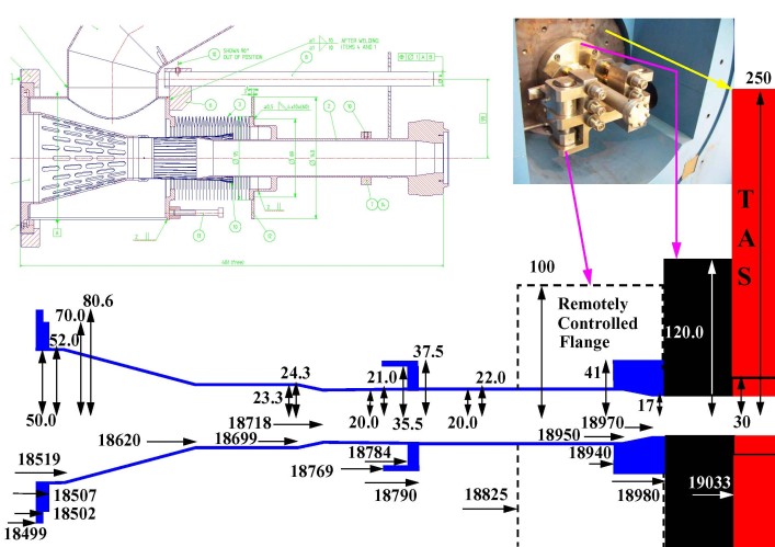
JD plug: R(mm)=0.01875(Z+149.33) for Z:6784-8864 mm
JT plug: R(mm)=0.01931(Z-55.54) for Z:8909-12585 mm
JFC1: R(mm)=0.00732(Z+23506) for Z:12969-18570 mm
JFC2: R(mm)=0.00747(Z+24777) for Z:12719-15799 mm
JFC3: R(mm)=0.01904(Z+166.85) for Z:15799-18530 mm
VJ cone: R(mm)=0.01920(Z-8863) for Z:14505-18605 mm
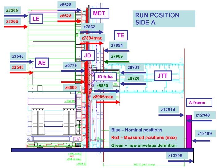
Length of endcap calorimeter is 318.5 cm. Nominal front and back of endcap calorimeter is at 354.0 cm and 672.5 cm
Nominal clearance between the back of the endcap calorimeter and the JD is 677.9 - 672.5 = 5.4 cm
Measured front of the endcap calorimeter = 354.5 cm on side A & 354.7 cm on side C
Adding 318.5 cm gives a measured back of the endcap calorimeter = 673.0 cm on side A and 673.2 cm on side C
Measured clearance between the back of the endcap calorimeter and the JD is 680.0 - 673.0 = 7.0 cm on side A
Measured clearance between the back of the endcap calorimeter and the JD is 679.8 - 673.2 = 6.6 cm on side C
Front of the ECT is at 792.9 cm.
Clearance JD hub ECT is 792.9 786.9 = 6.0 cm (nominal to nominal).
Clearance JD tube JTT is 890.9 888.9 = 2.0 cm (nominal to nominal).
Measured end of JD tube = 890.5 cm (side A) % 890.6 cm (side C).
Measured clearance JD tube JTT is 890.9 890.5 = 0.4 cm on side A (measured to nominal).
Measured clearance JD tube JTT is 890.9 890.6 = 0.3 cm on side C (measured to nominal).
The lengths of the JD tube on side C,
as measured by the surveyors,
is 2106.8+-0.6mm.
The errors here indicate the range of the measurements.
The nominal lengths of the JD tube assembly is 2105.0 mm.
Back of the ECT is at 792.9 + 495.3 = 1288.2 cm (1291.4 envelope).
Front of the JFC1 is at 1296.9 cm (1293.9 envelope).
Nominal clearance ECT JFC1 is 1296.9-1288.2 = 8.7 cm.
Nominal clearance JTT JFC1 is 1296.9-1285.0 = 11.9 cm.
Measured clearance ECT - JFC1 = 8.5 cm (side A).
Measured clearance JTT - JFC1 = 9.5 cm (side A).
Back of the JF bridge is at 1857.0 cm (ledge not included).
Back of JFC3 is at 1853.0 cm.
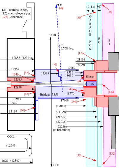
Front of the JN monobloc is at 1861.0 cm (surveyed position).
Nominal clearance JF bridge JN monobloc is 1861.0-1857.0 = 4.0 cm.
Nominal clearance JFC3 JN monobloc is 1861.0-1853.0 = 8.0 cm.
Measured clearance JFC1 - JN = 7.8 cm (side A) & 5.6 cm (side C).
Measured clearance JFC3 - JN = 8.7 cm - 9.5 cm (bottom - top on side C).
The lengths of the two JF bridges,
as measured by the surveyors,
are 5800.8+-0.8mm (with ledge) and 5602.0+-1.4mm (without ledge) for the first bridge
and 5801.2+-0.5mm (with ledge) and 5602.5+-0.8mm (without ledge) for the second bridge.
The errors here indicate the range of the measurements. The nominal lengths of
the JF bridge is 5801.0mm (with ledge) and 5601mm (without ledge).
STATUS
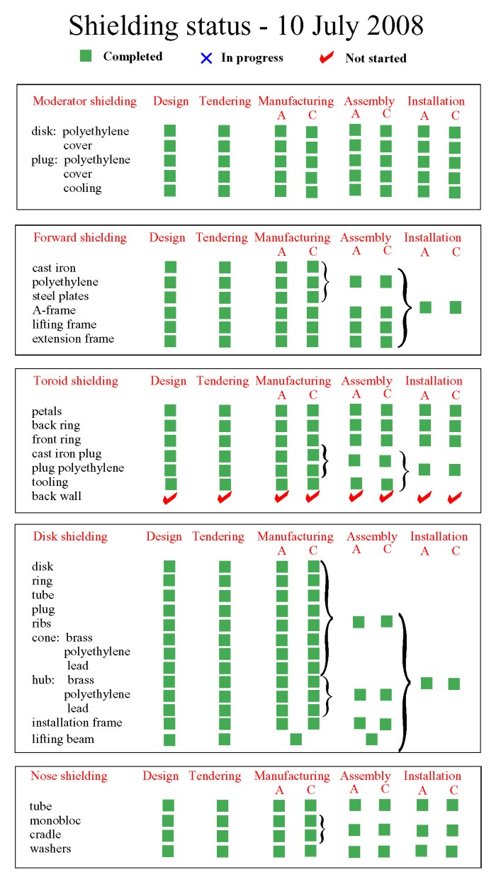
WORKPACKAGES
Back to the ATLAS home page
Last update:
15 March 2010


